In this guide
What needs to go on the wall sketch?
Stand square to the wall and make a front-view sketch. Record the finished wall boundaries, door and window casing, baseboard, outlets, switches, vents, controls, and anything that must open or be removed. Draw the face of each object, not just a dot at its center. A board can miss an outlet's center and still cover its plate.
Use the finished left edge as the horizontal reference and a marked floor point or level line as the vertical reference. Label both on the sheet and take every measurement from them. Record any slope in the floor or ceiling beside the sketch.
Measure the whole cover and its access space
For each obstacle, record its left, right, bottom, and top edges in one unit. Add how far it projects from the wall, what moves, and what must remain accessible. A door's casing footprint is different from its swing. A thermostat may need access beyond its visible face. A vent's required air space cannot be established from its outer dimensions alone.
Measure the installed cover while it remains in place. Leviton lists different footprints for standard and midway plates, so use the size on your wall rather than a generic outlet size. If you will replace the cover, measure the replacement before settling the layout.
| Item | Left / right | Bottom / top | Check beyond the rectangle |
|---|---|---|---|
| Wall field | 0 / 144 | 0 / 60 | End conditions and rail positions |
| Outlet plate | 48 / 51 | 16 / 20.5 | Access to the complete plate |
| Chosen drawing margin | 47.5 / 51.5 | 15.5 / 21 | 0.5-inch planning margin around this example |
Does the board overlap the outlet?
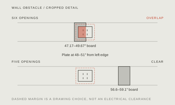
Suppose the wall is 144 inches wide and every vertical board is 2.5 inches wide. One board sits at each end. With six clear openings, there are seven boards. Clear gap = [144 − (7 × 2.5)] ÷ 6 = 21.0833 inches. The repeating distance from one board's left edge to the next is 21.0833 + 2.5 = 23.5833 inches.
Number the first board 0. Board 2 begins at 2 × 23.5833 = 47.1667 inches and ends at 49.6667 inches. The example plate occupies 48 through 51 inches, so their horizontal overlap is 49.6667 − 48 = 1.6667 inches. If the batten also crosses the plate's height, the layout has a conflict. Rounding the board position to a convenient fraction will not solve an overlap this large.
For two rectangles, check both directions. There is a conflict when their horizontal intervals overlap and their vertical intervals overlap. A horizontal rail may clear a plate left to right only because it is entirely above or below it. Keep the height check visible on the drawing.
Five openings clear this outlet
Try five openings using the same wall and board width. Six boards occupy 15 inches, leaving 129 inches of clear space. Each opening is 129 ÷ 5 = 25.8 inches, and the repeating distance is 28.3 inches. The board left edges are 0, 28.3, 56.6, 84.9, 113.2, and 141.5 inches.
The plate at 48–51 inches now falls between a board ending at 30.8 inches and the next beginning at 56.6 inches. Its right edge has 5.6 inches of space. Allowing a half-inch drawing margin leaves 5.1 inches. Now run the same check for each remaining outlet, switch, vent, and rail.
| Clear openings | Vertical boards | Clear gap | Result at the example plate |
|---|---|---|---|
| 6 | 7 | 21.0833 in | Board 2 overlaps the plate |
| 5 | 6 | 25.8 in | Plate sits between boards |
How much space belongs around the obstacle?
The half-inch margin in this drawing reserves visual breathing room around the plate. Label it as a design margin. Electrical access and equipment ventilation requirements must be checked separately.
Keep the complete cover accessible and leave the space required by the device or vent. If the proposed trim requires moving or extending an electrical device, either change the pattern or have an electrician assess the work before proceeding.
Check the trim in three dimensions
Tape the entire board width on the wall, including the rails. Open nearby doors and cabinet fronts. Put the furniture back in its intended position. Check that a rail does not meet a control, cover the edge of a vent, or leave a small strip of wall that will be awkward to paint.
Hold a trim sample beside the baseboard and door casing. Look from the side: will the batten project past either edge? Decide how the transition will finish before ordering. When wall widths differ at the top and bottom, mark where the end gaps or trim will absorb the difference.
When the layout is ready for a cut list
Date the selected drawing and record the board face width, treatment height, rail arrangement, and any intentional unequal openings. Measure the finished cut lengths from that arrangement. If you move a board, revise the adjoining openings and the cut list at the same time.
Enter the measured obstacles into the planner’s obstruction check, then verify the selected pattern against the physical wall before using its quantities. Review EPA’s lead-safe renovation guidance before disturbing painted surfaces in an older home.
Entering the coordinates in the planner
Open the accent wall planner, enter the treatment dimensions, and scroll to the obstruction check. Add every measured rectangle from the same bottom-left origin. Compare the current layout with nearby opening counts. Export or print the obstruction record before leaving: the main Save project action saves the wall inputs but does not include that record.